High speed digital measurement, SI/PIHispeed digital measurement solutionProductSolution

Broadband PCB connector & cable

HSDT(High Speed Digital Testing)

MMPX boasting 67 GHz band with coaxial cable ~ PCB connection,
And MXP which can aggregate up to 16 coaxial ports,
High-speed serial interface evaluation board and high-frequency measurement
It is a solution for the system.

ATE service, HUBER + SUHNER covers a wide range
Among genres, HSDT (High Speed Digital Testing)
It is an authorized dealer in charge of product department.

MMPX (67 GHz / 80 Gbps miniature)

Boasting the industry's highest bandwidth of 67 GHz for coaxial cable to PCB connectors,
It is a flagship product of HUBER + SUHNER.

Easy mating with snap-on
· Connection stability by original structure (patent)
· Minimum 5.08 mm pitch Adjacent mounting possible

· Characteristic impedance: 50 Ω
· Return loss: <-16 dB @ 67 GHz
(For edge mount / microstrip connection)

· Straight (vertical, edge mount)
· Right angle

· SI support
- S parameter (representative characteristic)
- Evaluation kit
- Example of footprint design
- Footprint optimization
- Implementation Guide
- 3D Geometry Model
- Board level simulation
- Cable measurement

· Corresponding cable (HUBER + SUHNER)
- MULTIFLEX 86 HE
- MULTIFLEX 53-02
- SUCOFORM 86
- EZ 86
- minibend L
· End connector: MMPX, PC 1.85,
PC 2.4, SK (2.92 mm)
• Isometric assembly: ± 1 pS
· Adapter: PC 1.85, SK (2.92 mm)

MXP (50/40/18 GHz multicorex)

Connect up to 16 coaxial ports (single ended) at once, MXP_all.png
It made it possible to save space on the evaluation board and reduce the number of measurement steps.
According to the measurement object, from 3 classes of band 50 GHz / 40 GHz / 18 GHz
You can choose.

Easy attachment / detachment by push-on / pull-off
· 4 mm pitch / 1 × 8 = 8, 2 × 8 = 16 array
· MXP 50 / MXP 40 / MXP 18 mating compatibility

· Cable (HUBER + SUHNER) MXP_board.jpgMXP_2x8_breakout.png
- MULTIFLEX 53-02
• Isometric assembly: ± 2 pS

· SI support
- S parameter (representative characteristic)
- Evaluation kit
- Example of footprint design
- Footprint optimization
- Implementation Guide
- Board-level simulation MXP50_RL.gif
- Cable measurement

MXP50

· Characteristic impedance: 50 Ω MXP 50 _ PCB.png MXP 50 _ cable.png
· Return loss: · Breakout end:
- MMPX
- PC 2.4
- MXP 50 (jumper)

MXP18

· Characteristic impedance: 50 Ω
· Return loss: <-12 dB @ 40 GHz · Breakout end: - SK (2.92 mm) - MXP 40 (jumper)

MXP40

· Characteristic impedance: 50 Ω
· Return loss: <-12 dB @ 40 GHz · Breakout end: - SK (2.92 mm) - MXP 40 (jumper)

SMPM-T (SMPM compatible, enhanced stability)

MIL-STD-348 SMPM connection / fitting stability SMPM-T.png
Improved, we developed our own SMPM-T.

· Lock mechanism by screw nut
· Connection stability / Improvement of attachment / detachment life
· SMPM compatible

· Characteristic impedance: 50 Ω
· Frequency range: DC ~ 67 GHz

· Microbend cable assembly

· SI support
- Example of footprint design
- Footprint optimization
- Board level simulation
- Cable measurement

Minibend / microbend (18 to 90 GHz low profile cable assembly)

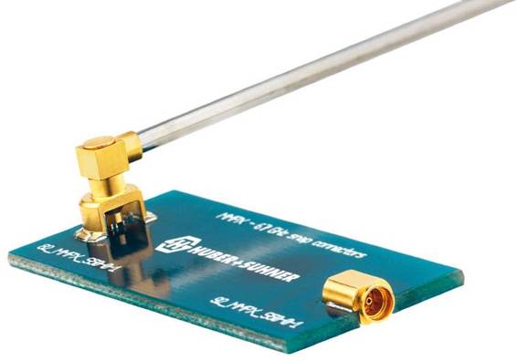
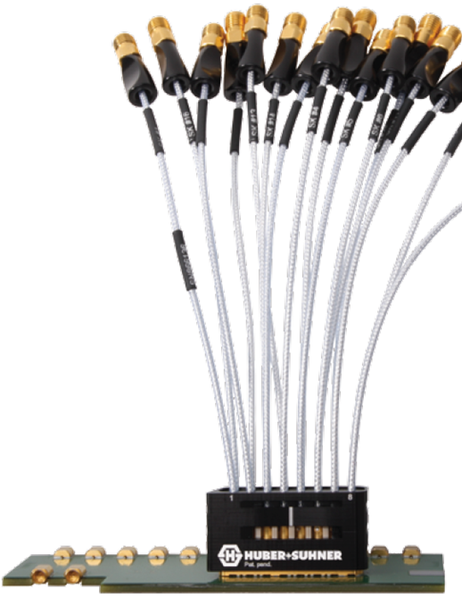
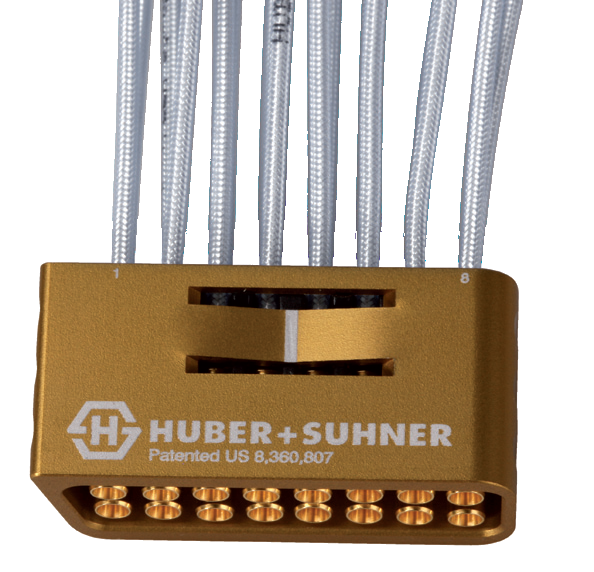
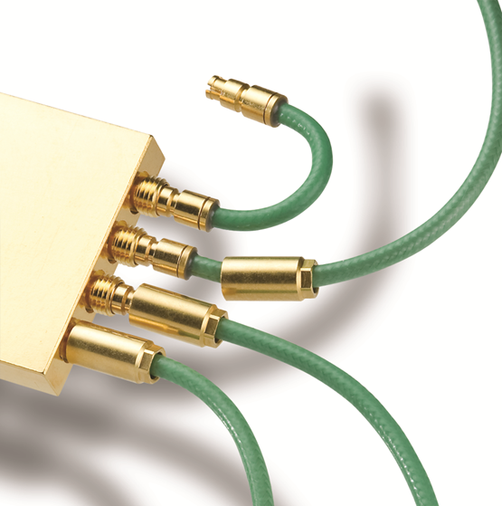
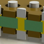
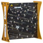
With solderless inner contact technology, tight bending was made possible,
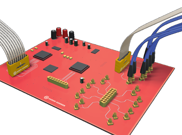
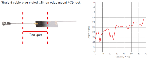
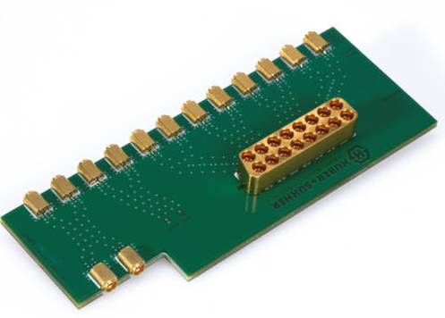
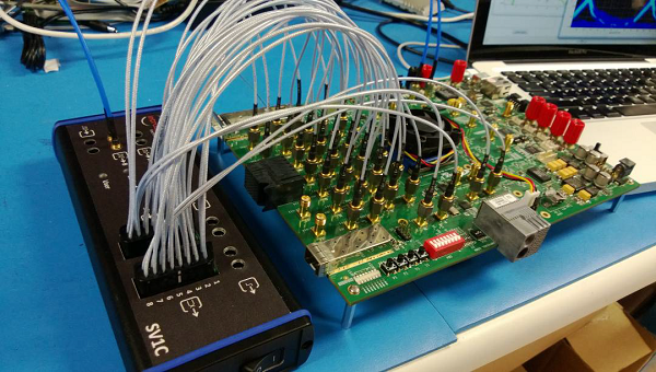
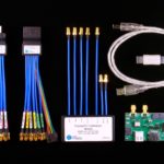
It is a high frequency cable assembly. In addition to securing phase stability and high shielding performance,
Wiring length design / preforming semirigid cable or right angle connector
It also contributes to cost improvement in multichannel test environment, such as making it unnecessary.

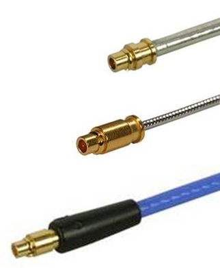
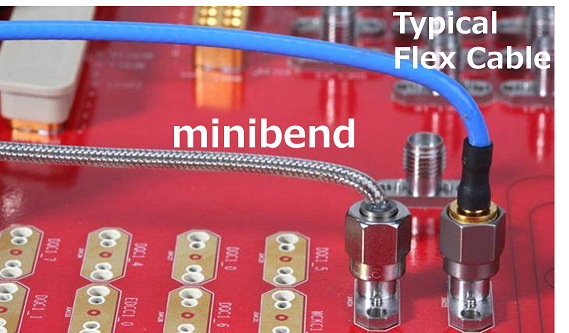
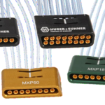
Minibend: ~ 65 GHz, minimum bend radius 5.08 mm minibend_vs_typical_flex.jpg.png

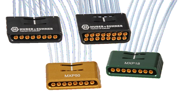
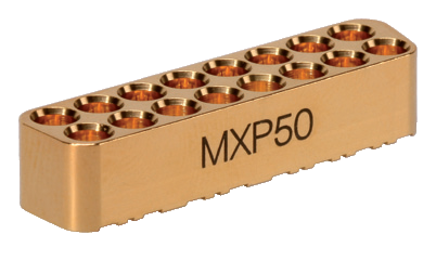
· Microbend: ~ 90 GHz, minimum bend radius 1.52 mm,
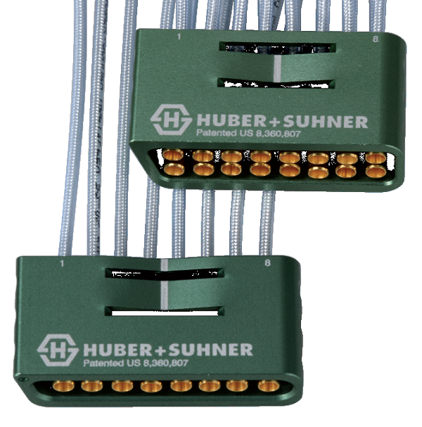
                     SMPM-T connectable, 1.0 mm connectable